Introduction#
Serial intro#
Differential car is a common structure in robot base. There are extended tutorial ranging from modeling to simulation using ROS2 and related tools. However, these tutorial mainly using Gazebo classic, an obsolete version of simulator. Though Gazebo has been updated to Ionic and introduced many new features, seldom tutorial introduce complete workflow from building a differential car model, adding control plugins, loading model to Gazebo, visualize model in Rviz and control the model by publishing commands OR using game pad.
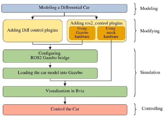
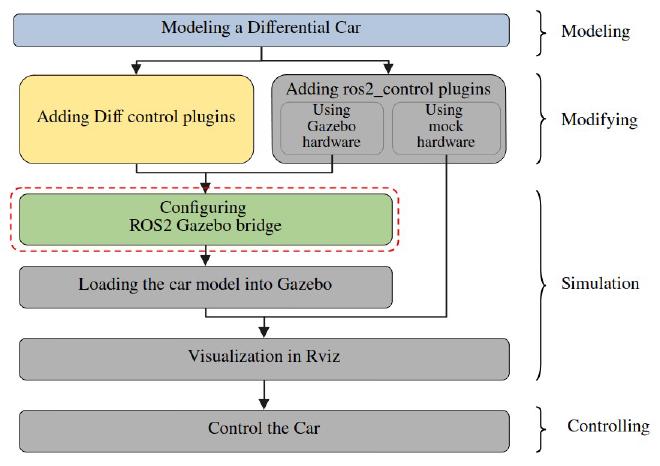
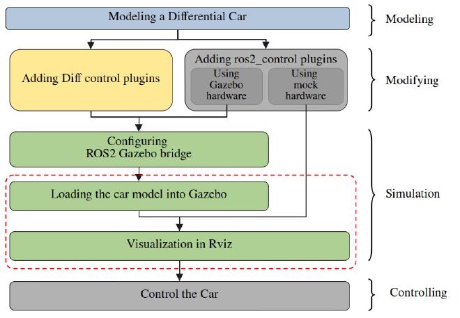
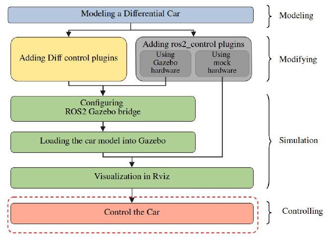
This serial introducing a complete workflow, introducing how to simulate a differential car model in Gazebo Harmonic. No hardware is requested in this tutorial, but you can add hardware easily later. The serial’s syllabus is shown below.
The software used are listed below:
| Software | Version |
|---|---|
| OS | Ubuntu 24.04 |
| ROS | Jazz Jalisco |
| ros2_control | 4.20.0-1noble.20241118.193738 |
| Gazebo | Harmonic |
| Rviz | 14.1.5-1noble.20241115.194822 |
Source code could be found here
About this tutorial#
In this tutorial, we will build a differential car model and using diff drive system plugin to control the car.
Modeling#
Section overview#
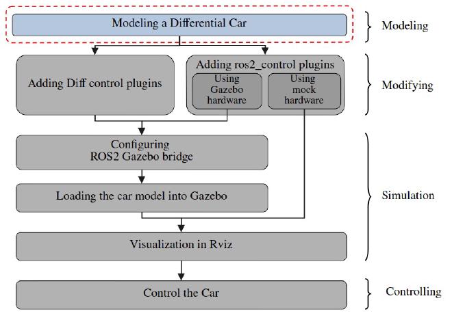
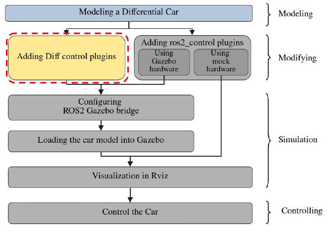
What we are doing is framed with dashed red line, what we have done are colored, what we haven’t done are grey.
In this section, we wil build a differential drive car model with a IMU sensor, a lidar, and a depth camera. The structure is identical to the model provide by FishROS.
The robot we will create looks like:
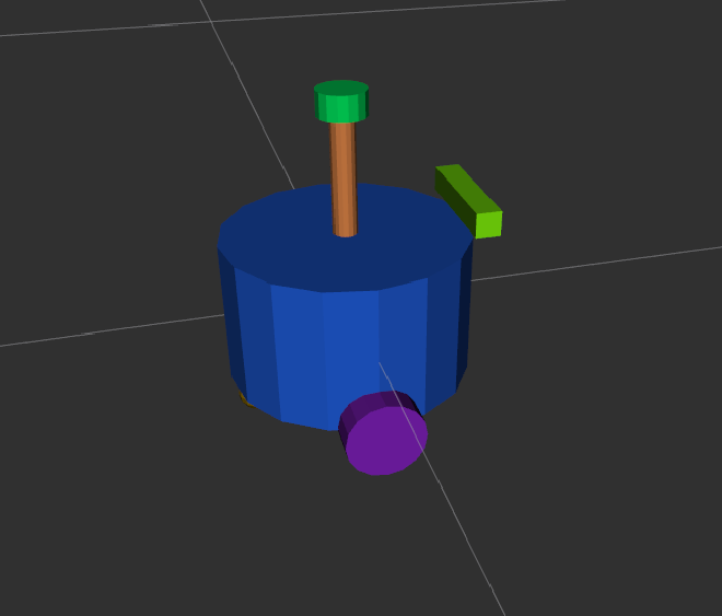
It has structure like:

Tools#
- URDF Creator
- URDF Checker
- VS code
Steps#
Creating ROS2 robot description packages#
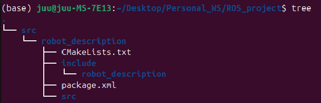
We usually separate the robot description and robot control packages for better scalability and reusability. First creating a robot description, in your ROS2 workspace root folder, run:
ros2 pkg create robot_description --build-type ament_cmake --destination-directory src
We create a package named robot_description in the src folder. you workspace should has structure:
Open VS code in your ROS2 workspace:
code .
Creating a sdf, and launch folder under robot_description folder, you will get following file structure in vscode:
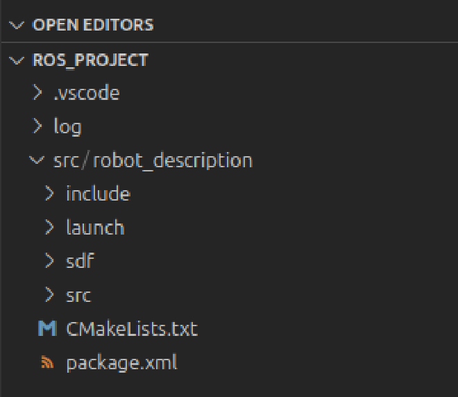
the sdf folder will be used to store robot description file and the launch folder will be used to launch Rviz preview.
Creating the robot description file on URDF Creator webpage#
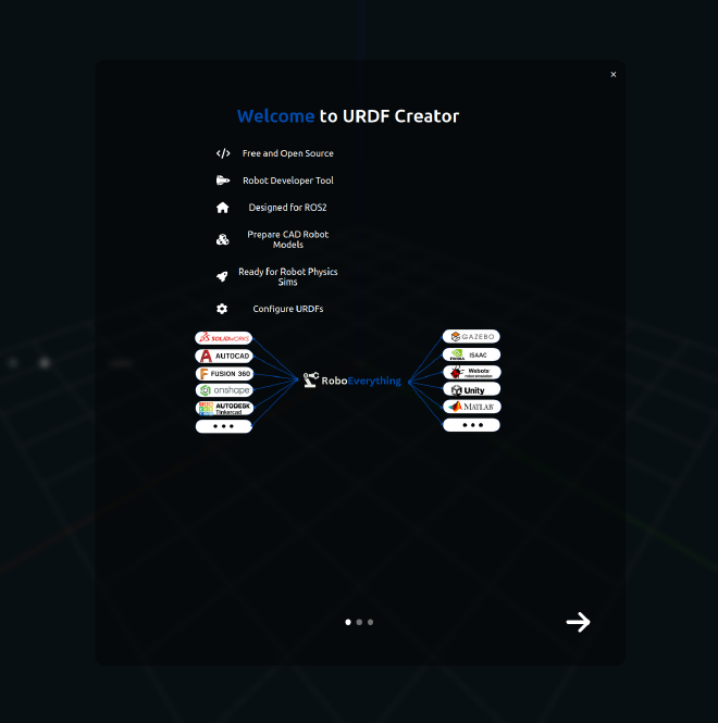
URDF creator is a open source webpage application created by lever robotics, it can import almost all 3D models and output URDS ,SDF file or entire robot description ros2 packages. It can also modeling simple robot structure on the webpage.
Start the project#
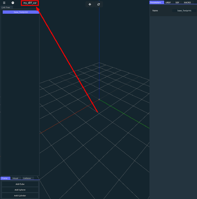
Close the welcome page, the web app automatically create a base_footprint for us:
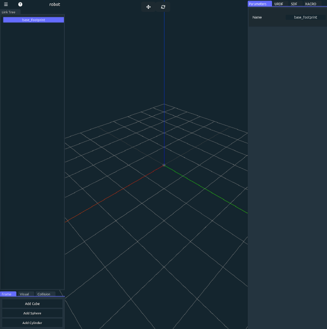
Get familiar with the webpage and we will start create the robot.
Rename the robot#
Rename the robot on the right top.
Add base link#
Add a cylinder as base link, drag and put it under base_footprint in Link Tree panel. We change the following parameters and keep other default. Attention that we have to change both visual and collision cylinder’s radius and height, the screenshot below does not show collisions’ size.
| Feature | Value |
|---|---|
| Radius | 0.1 |
| Height | 0.12 |
| Position, z | 0.1 |
| Mass | 200 |
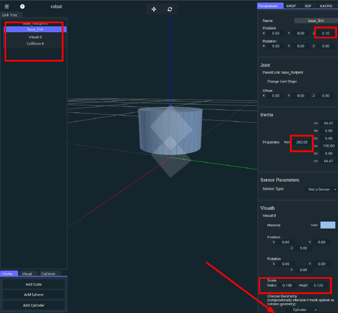
There will be a cylinder base lik in the screen, check URDF and SDF on the right panel, there has been some automatically generated code.
Save the project file#
To save the file we have currently create, click the up right three bar -> Export -> Save Project, and Export a GLTF file. It will create a GLTF file that save our project and reopen to continue the job.
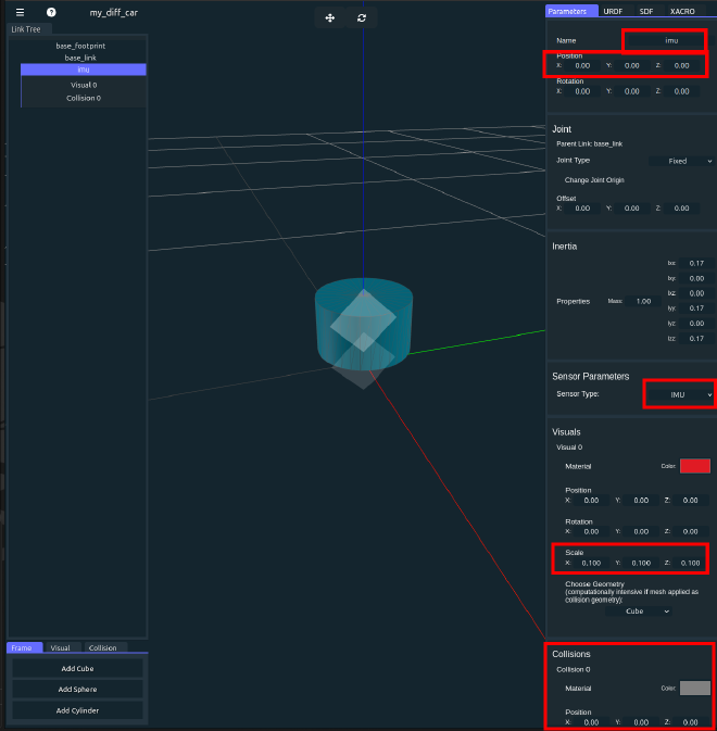
Add imu sensor#
Add a cube link as imu, drag and put it under base_link, changing following parameters:
| Feature | Value |
|---|---|
| Name | imu |
| Position, x | 0 |
| Position, y | 0 |
| Position, z | 0 |
| Scale, x | 0.1 |
| Scale, y | 0.1 |
| Scale, z | 0.1 |
| Sensor Type | IMU |
We hide the imu link inside the base_link, so we cannot see it directly. But check out the URDF or SDF code, we could find the imu link. Also, we set the sensor type as IMU, and till i write this blog, there are some bugs in the web: after choosing sensor type as IMU, it will not show immediately, unless you switch to other tags then switch back to Parameters tag.
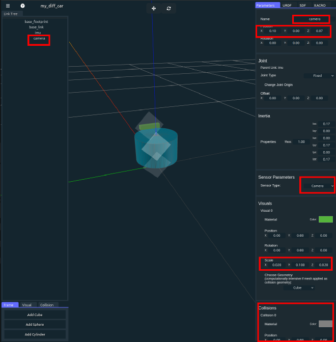
Add camera sensor#
Add a cube link as camera, drag and put it under base_link, changing following parameters:
| Feature | Value |
|---|---|
| Name | camera |
| Position, x | 0.1 |
| Position, y | 0 |
| Position, z | 0.07 |
| Scale, x | 0.02 |
| Scale, y | 0.1 |
| Scale, z | 0.02 |
| Sensor Type | Camera |
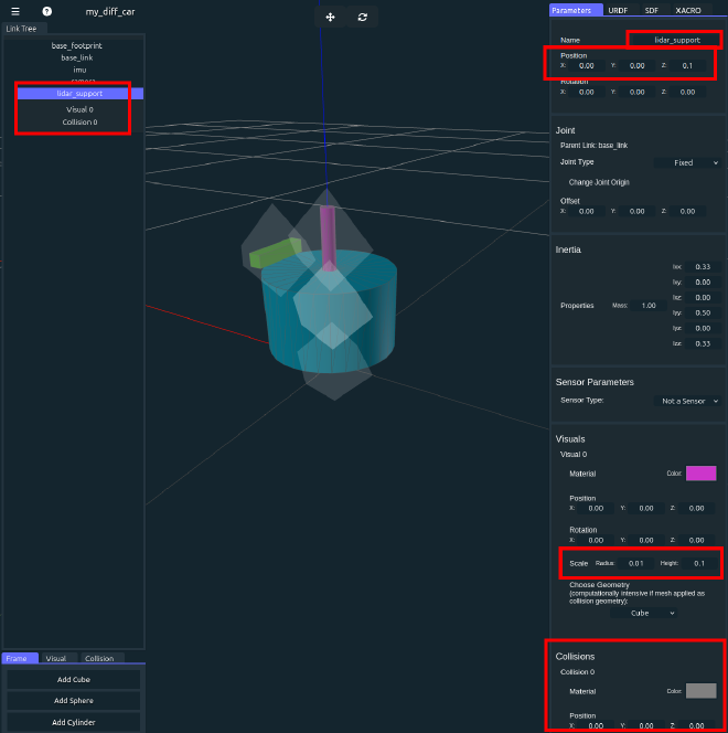
Add lidar support#
Though we can directly make lidar floating, we still add a lidar support to make the robot more reasonable. Add a cylinder link as lidar_support, drag and put it under base_link, changing following parameters:
| Feature | Value |
|---|---|
| Name | lidar_support |
| Position, x | 0 |
| Position, y | 0 |
| Position, z | 0.1 |
| Scale, Radius | 0.01 |
| Scale, Height | 0.1 |
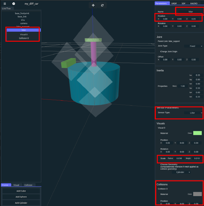
Add lidar sensor#
Add a cylinder link as lidar, drag and put it under lidar_support, changing following parameters:
| Feature | Value |
|---|---|
| Name | lidar |
| Position, x | 0 |
| Position, y | 0 |
| Position, z | 0.05 |
| Scale, Radius | 0.03 |
| Scale, Height | 0.01 |
| Sensor Type | Lidar |
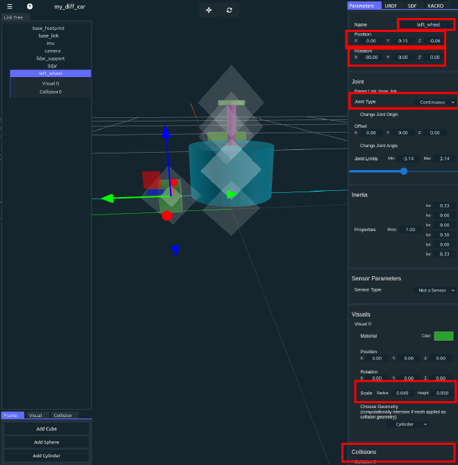
Add left wheel#
Add a cylinder link as left_wheel, drag and put it under base_link. Since the default cylinder is oriented vertically upwards, we need to rotate it to a horizontal orientation. The different rotation direction will cause the original z-axis to face left or right:

The left and right cylinder in the picture has different forward direction. When both cylinder(wheel) rotate along z-axis in counter clockwise, the left cylinder will going into the screen, and the right cylinder will going out the screen. That is when we send forward command to the car it may going backwards. To avoid this, make sure after rotation, the original z-axis is the same direction as y-axis. Usually, in 3D software, three axis have different color: Red - X, Green - Y, Blue - z. So make sure the original z-axis of wheel have the same direction as green axis shown in the app.
If you don’t understand above, just changing following parameters:
| Feature | Value |
|---|---|
| Name | left_wheel |
| Position, x | 0 |
| Position, y | 0.15 |
| Position, z | -0.06 |
| Scale, Radius | 0.04 |
| Scale, Height | 0.05 |
| Joint Type | Continuous |
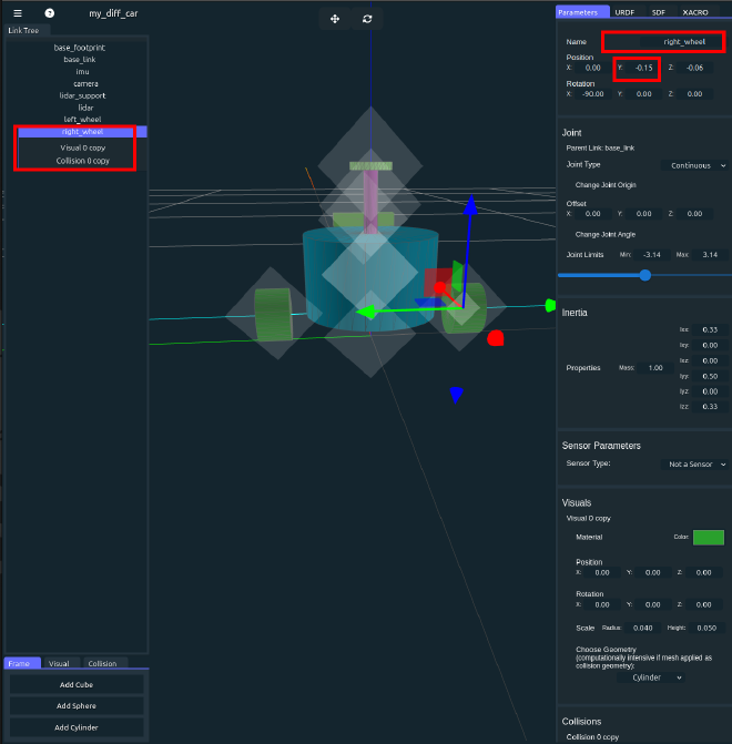
Add right wheel#
Add a cylinder link as right_wheel, drag and put it under base_link.You may find that the left and right wheel have the same parameters except the position y and the name, so we can duplicated lef wheel in Link Tree on the left panel and change these two parameters. Or you can changing following parameters if you build a new right wheel:
| Feature | Value |
|---|---|
| Name | right_wheel |
| Position, x | 0 |
| Position, y | -0.15 |
| Position, z | -0.06 |
| Scale, Radius | 0.04 |
| Scale, Height | 0.05 |
| Joint Type | Continuous |
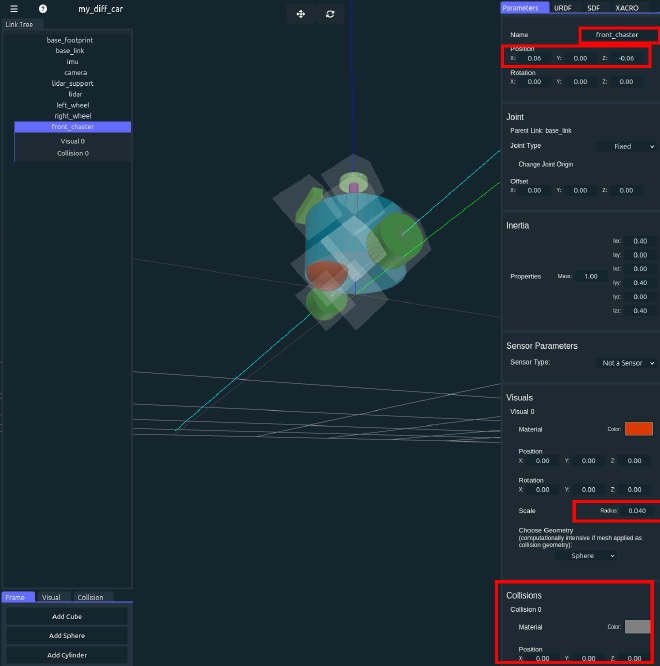
Add front chaster#
we need two chaster to make the car balance. Add a sphere ling as front_chaster, drag and put it under base_link.changing following parameters:
| Feature | Value |
|---|---|
| Name | front_chaster |
| Position, x | 0.06 |
| Position, y | 0 |
| Position, z | -0.06 |
| Scale, Radius | 0.04 |
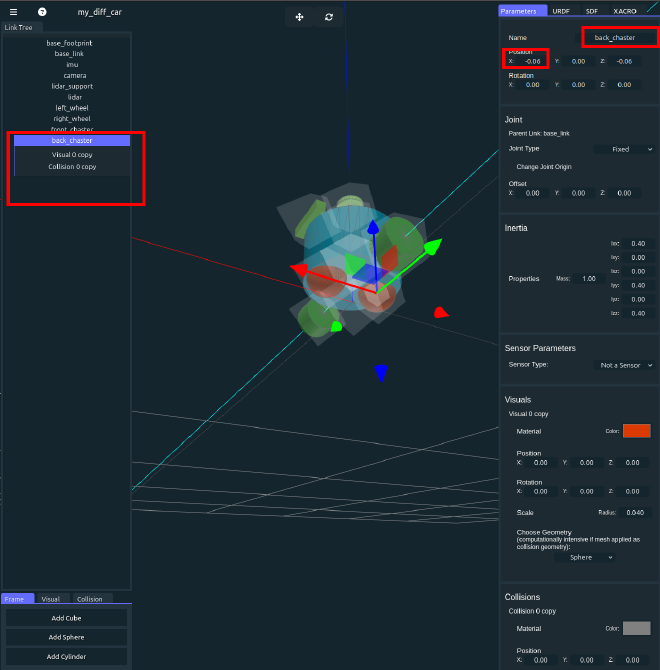
Add back chaster#
we need two chaster to make the car balance. Add a sphere ling as back_chaster, drag and put it under base_link.changing following parameters:
| Feature | Value |
|---|---|
| Name | back_chaster |
| Position, x | -0.06 |
| Position, y | 0 |
| Position, z | -0.06 |
| Scale, Radius | 0.04 |
Save the project and sdf file#
Save the project file by clicking three bars on the up right and choose Export. Then Save Project.
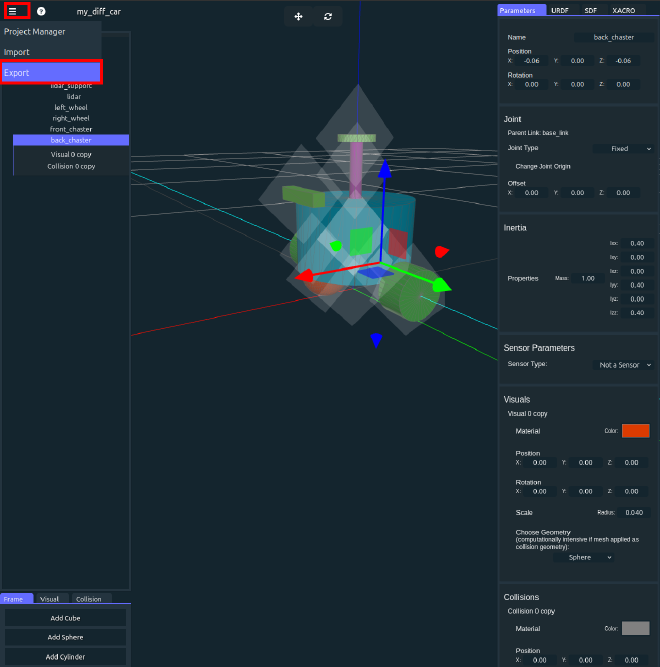
Creating a .sdf file under sdf folder in vscode, then paste all sdf content from the web app
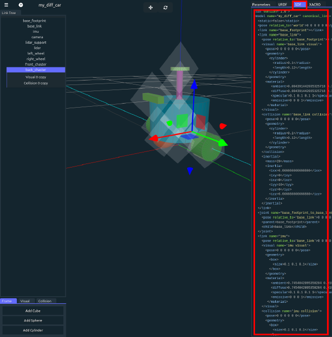
Check the model#
You have finished the modeling! But before use the model, we will do a final check to avoid potential mistakes in the model.
Export the model as URDF file, then use Chrome browser open the urdf check website. Drag and drop the URDF file into the page. You will see our model is loaded and two wheels are controllable.
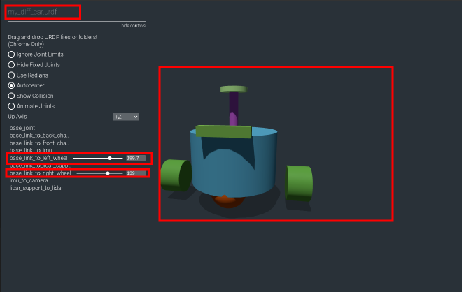
Congratulations! You build a differential car. We will modifying the car in the next section to fit the new Gazebo.
Modifying#
Section overview#
In last section, we have created a differential car and generate .sdf file. Unfortunately, the .sdf file is generated to load in old version of Gazebo. In this section, we will modify the .sdf file to compatible with Gazebo Harmonic, the newest LTS version.
Tools#
- VS code
Steps#
We will add a Diff control plugin, modify the joint state publisher plugin and sensor in sdf file. The Diff control plugin allow us to control the car, joint state publisher auto publish the joint state from Gazebo, and sensor publish sensor date from Gazebo.
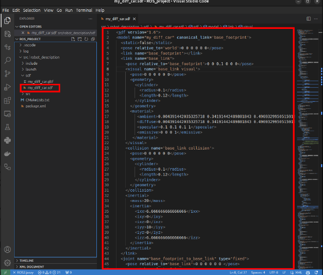
Check the sdf file#
Check the .sdf file, we will find that some sensor tag are added to corresponding link, searching imu in the .sdf file we will find that a sensor named imu is added under imu link. Check other sensor tag in the file by yourself.
We also find that at the end of .sdf file, there is a joint_state_publisher plugin, which will publish the joint state in Gazebo.
The automatically generated plugin was designed to work in Gazebo classic. The detailed explanation can be found in official documents. You can also find some useful information about migration sensor plugin to Gazebo Harmonic.
Modify the pose#
At the beginning of .sdf file, we could find:
<pose relative_to='world'>0 0 0 0 0 0</pose>
Just delete it for compatibility.
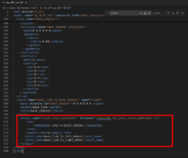
Modify the joint state publisher plugin#
Going to the end of .sdf file, changing the plugin code to the following to use in Gazebo Harmonic:
<plugin name="gz::sim::systems::JointStatePublisher" filename="gz-sim-joint-state-publisher-system">
    <topic>joint_states</topic>
    <joint_name>base_link_to_right_wheel</joint_name>
    <joint_name>base_link_to_left_wheel</joint_name>
</plugin>
the topic tag assign the joint state publish topic and joint_name assign which joint information we will publish in Gazebo. Since other joints are fixed, we only need to publish the wheel joints. Make sure the joint name is identical to your .sdf file.
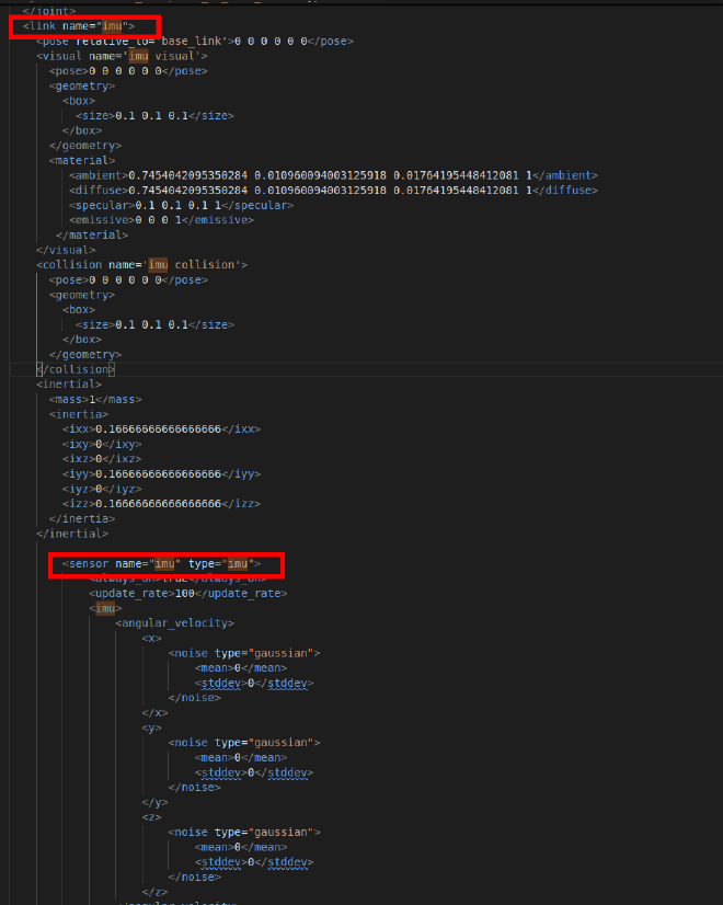
Modify imu sensor#
Search sensor in .sdf file, find codes related to imu. We will find that in imu’s sensor tag, there is a plugin named imu_plugin_for_imu, and file name libgazebo_ros_imu_sensor.so (you may have different plugin name, but the filename should be the same):
<plugin name="imu_plugin_for_imu" filename="libgazebo_ros_imu_sensor.so">
    <ros>
        <remapping>~/out:=imu/imu</remapping>
    </ros>
</plugin>
this plugin is used in Gazebo classic to publish imu date. We will handel the sensor date in a world plugin in Gazebo Harmonic. So:
- delete the imu
plugincode here. - Also add a
topictag under sensor tag to assign the gazebo imu topic:
<topic>imu</topic>
The final code related to imu sensor is (for simplicity we’ve omitted the content in imu tag):
      <sensor name="imu" type="imu">
        <always_on>true</always_on>
        <update_rate>100</update_rate>
        **<topic>imu</topic>**
        <imu>
            XXXXXXXXXXXXXXXXXXXX
            XXXXXXXXXXXXXXXXXXXx
            ......
        </imu>
      </sensor>
Modify camera sensor#
Search sensor in .sdf file, find codes related to camera. We will find sensor tag related to camera and it’s plugin.
To make the robot more functional, we will use a depth camera. So:
- change the sensor type to
rgbd_camera, - add a
topictag under sensor to assign the camera date topic - for the same reason, delete the
plugintag under sensor - Add
gz_frame_idunder sensor for new Gazebo - add
camera_info_topicunder camera tag for new Gazebo
The final code related to camera sensor is:
<sensor name="camera_camera" type="rgbd_camera">
    <always_on>true</always_on>
    <visualize>true</visualize>
    <update_rate>100</update_rate>
    <topic>camera</topic>
    <gz_frame_id>camera</gz_frame_id>
    <camera name="camera_camera">
        <camera_info_topic>camera/camera_info</camera_info_topic>
        <horizontal_fov>1.3962634</horizontal_fov>
        <image>
        <width>800</width>
        <height>600</height>
        <format>R8G8B8</format>
        </image>
        <clip>
        <near>0.1</near>
        <far>100</far>
        </clip>
        <noise>
        <type>gaussian</type>
        <mean>0</mean>
        <stddev>0.007</stddev>
        </noise>
    </camera>
</sensor>
Modify lidar sensor#
Search sensor in .sdf file, find codes related to lidar. We will find sensor tag related to lidar and it’s plugin.
To use the lidar sensor in new Gazebo, change following:
- change sensor type to
gpu_lidar - add a
topictag under sensor - delete the
plugintag under sensor - Add
gz_frame_idunder sensor - change
raytag tolidar
The final code related to lidar sensor is:
<sensor name="lidar_lidar" type="gpu_lidar">
    <always_on>true</always_on>
    <visualize>true</visualize>
    <pose>-0.064 0 0.121 0 0 0</pose>
    <update_rate>5</update_rate>
    <topic>scan</topic>
    <gz_frame_id>lidar</gz_frame_id>
    <lidar>
        <scan>
        <horizontal>
            <samples>360</samples>
            <resolution>1</resolution>
            <min_angle>0</min_angle>
            <max_angle>6.28</max_angle>
        </horizontal>
        </scan>
        <range>
        <min>0.12</min>
        <max>3.5</max>
        <resolution>0.015</resolution>
        </range>
        <noise>
        <type>gaussian</type>
        <mean>0</mean>
        <stddev>0.01</stddev>
        </noise>
    </lidar>
</sensor>
Add Differential drive plugin#
We want to use a differential drive to control our car, to do this, add a differential drive plugin under inside model tag , alone side the joint state publisher plugin:
<plugin filename="gz-sim-diff-drive-system" name="gz::sim::systems::DiffDrive">
    <left_joint>base_link_to_left_wheel</left_joint>
    <right_joint>base_link_to_right_wheel</right_joint>
    <wheel_separation>0.3</wheel_separation>
    <wheel_radius>0.04</wheel_radius>
    <max_linear_acceleration>0.033</max_linear_acceleration>
    <odom_topic>odom</odom_topic>
    <topic>cmd_vel</topic>
    <frame_id>odom</frame_id>
    <child_frame_id>base_footprint</child_frame_id>
    <odom_publisher_frequency>30</odom_publisher_frequency>
    <tf_topic>/tf</tf_topic>
</plugin>
The plugin will run in gazebo to receive control command and publish odom information. Make all joints name, frames name and wheel parameters set here is identical to your car.
Till now, we have completed our car model. Before we moving on, we will check the model again. We are going to load the model into the Rviz to do some final check.
Check in Rviz#
- Build a .py file in the
launchfolder, the file name could bepreview.launch.py. - To store the Rviz config file in the future, we could also create a
configfolder along side launch folder.
The .launch.py file should have following content:
import launch
import launch_ros
from ament_index_python.packages import get_package_share_directory


def generate_launch_description():
    robot_description_path = (
        get_package_share_directory("robot_description") + "/sdf/my_diff_car.sdf"
    )
    rviz_config_path = (
        get_package_share_directory("robot_description") + "/config/rviz_config.rviz"
    )

    return launch.LaunchDescription(
        [
            launch_ros.actions.Node(
                package="robot_state_publisher",
                executable="robot_state_publisher",
                output="screen",
                parameters=[{"robot_description": open(robot_description_path).read()}],
            ),
            launch_ros.actions.Node(
                package="rviz2",
                executable="rviz2",
                arguments=["-d", rviz_config_path],
            ),
        ]
    )
We read the sdf file content and publish it.
- Edit the
CmakeLists.txtfile to install our sdf model and launch file, add this under find_package:
install(DIRECTORY launch config sdf
  DESTINATION share/${PROJECT_NAME})
- compile the project using
colcon. Open the terminal under project workspace:
colcon build --symlink-install
here we use symlink install for convince.
- source the bash and launch the Rviz:
source install/setup.bash
ros2 launch robot_description preview.launch.py
You will find Rviz is launch and nothing appears. We need to manually add robot to the Rviz. Click Add at left bottom -> RobotModel
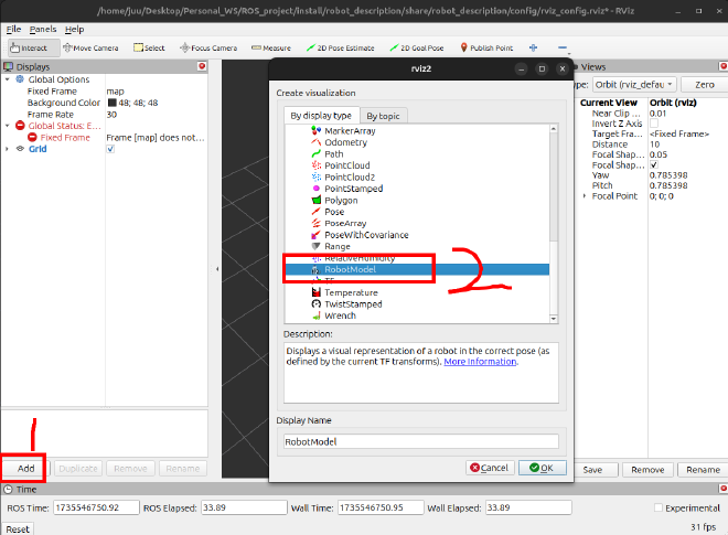
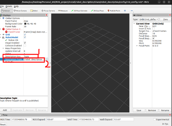
Then expand RobotModel, choose Description Source as Topic and set the Topic as robot_description.
The robot still does not show correctly, since we choose wrong Fixed Frame. Select Fixed Frame as base_footprint, the robot should show with Error.
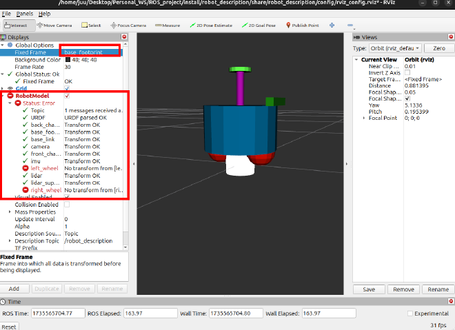
Two wheel does not show correctly, it is ok since we do not publish any wheel information. We will fix it after launch Gazebo.
It is tedious to set the Robot Model and choose Fixed Frame manually every time. Lucky, we have already set the rviz config file when launch. So save the current Rviz config to our config folder.
Select File on up left, then save Config As choose the config folder and name as rviz_config.rviz. The file name should correspond to our launch file.
Since we use symlink-install, we do not need compile again. Launch the launch file, then Robot model is loaded automatically.
We finally made it! the robot model all set. And we will load the robot into Gazebo.
Config ros_gz_bridge#
Section overview#
Before loading and simulating the model in gazebo, we should add a bridge between ROS2 and Gazebo. We config all the plugin and sensor before to fit gazebo, and all the date is published in Gazebo, to read these sensor date in ROS2 we should transfer the date from Gazebo to ROS2. ros_gz_bride is designed to do thar for us.
In this section we will setup simulation packages and setup bridge config file.
Tools#
- VS code
Steps#
Build simulation package#
- Create a separate ros2 package for simulation. In the workspace, run:
ros2 pkg create diff_sim --build-type ament_cmake --license Apache-2.0 --destination-directory src
here we create a package named diff_sim in src folder.
the workspace structure should look like:
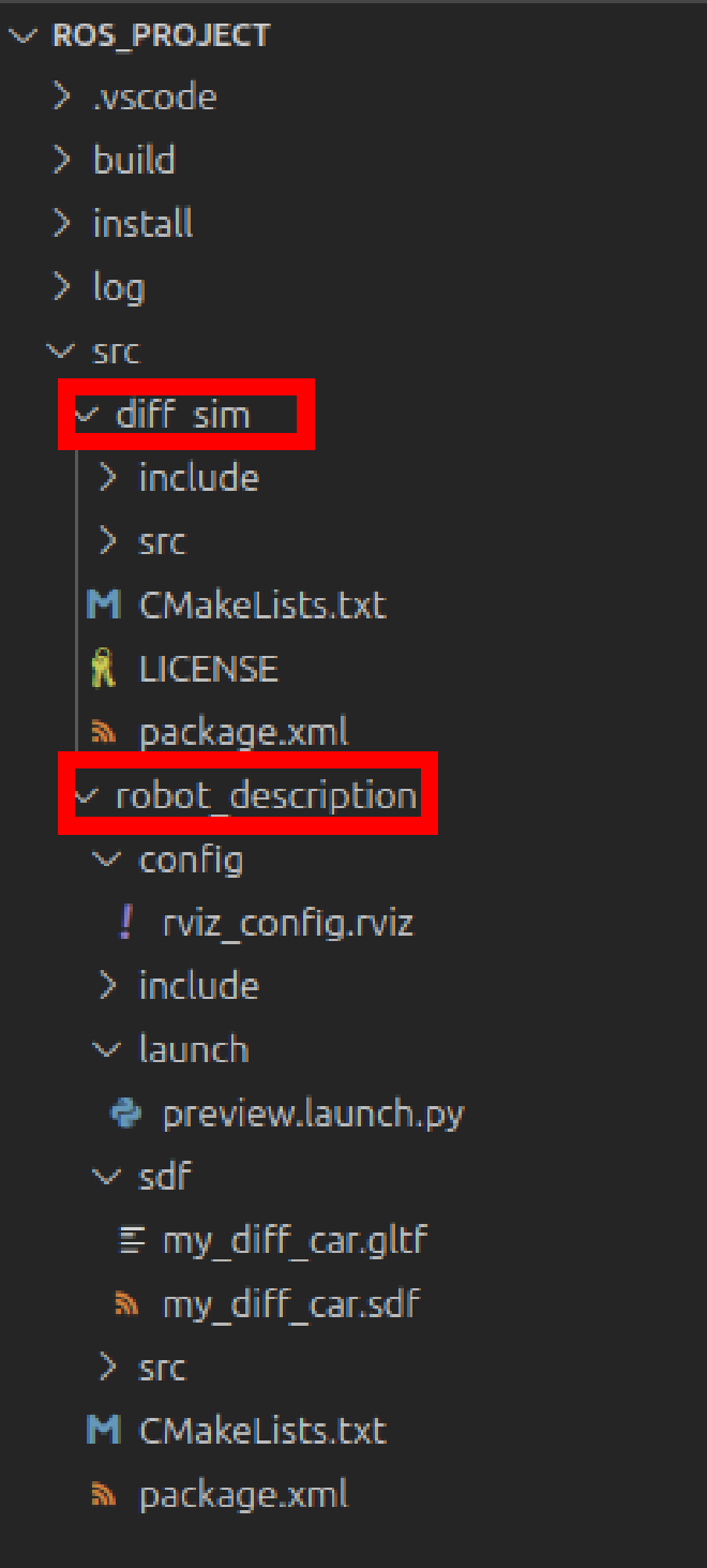
under src folder, there is a robot_description folder that contain robot description file and a newly created diff_sim folder to run the simulation.
- Create
launch,configandworldsfolders underdiff_simfolder for further use.
launch folder will store launch file, config folder will store all configuration file, worlds folder will store the world file in gazebo.
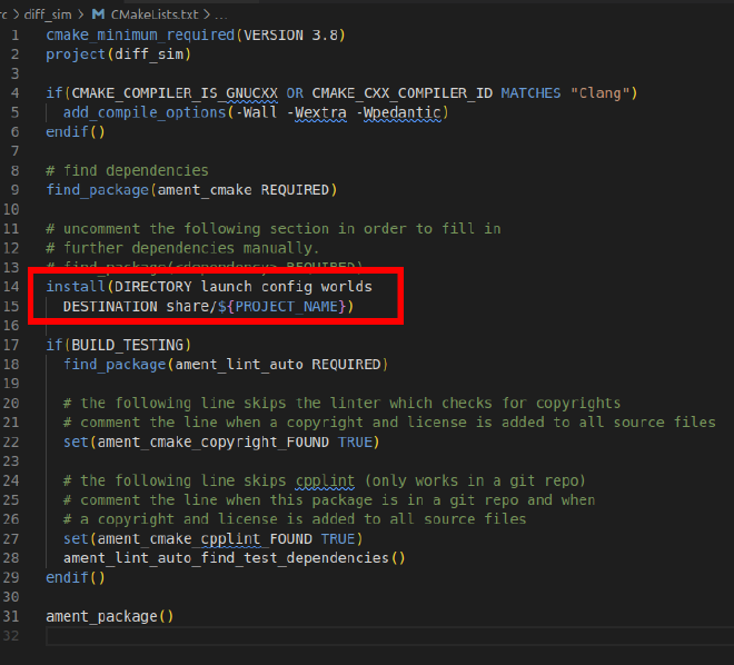
- Install these folder in
CMakeLise.txtfile, add:
install(DIRECTORY launch config worlds
  DESTINATION share/${PROJECT_NAME})
your cmake file should looks like:
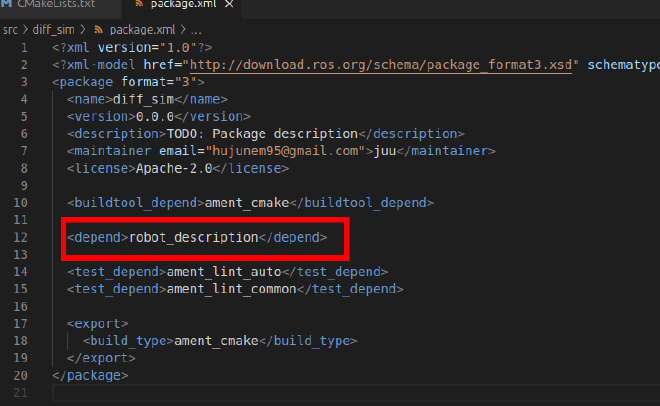
- Since we will use the robot description file in
robot_descriptionpackages, add it inpackage.xmlbeforeexporttag:
<depend>robot_description</depend>
your package.xml should looks like:
Add bridge config file#
Creating a new file under config folder named bridge_config.yaml, paste to the file:
# gz topic published by the simulator core
- ros_topic_name: "clock"
  gz_topic_name: "clock"
  ros_type_name: "rosgraph_msgs/msg/Clock"
  gz_type_name: "gz.msgs.Clock"
  direction: GZ_TO_ROS

# gz topic published by JointState plugin
- ros_topic_name: "joint_states"
  gz_topic_name: "joint_states"
  ros_type_name: "sensor_msgs/msg/JointState"
  gz_type_name: "gz.msgs.Model"
  direction: GZ_TO_ROS

# gz topic published by DiffDrive plugin
- ros_topic_name: "odom"
  gz_topic_name: "odom"
  ros_type_name: "nav_msgs/msg/Odometry"
  gz_type_name: "gz.msgs.Odometry"
  direction: GZ_TO_ROS

# gz topic published by DiffDrive plugin
- ros_topic_name: "tf"
  gz_topic_name: "tf"
  ros_type_name: "tf2_msgs/msg/TFMessage"
  gz_type_name: "gz.msgs.Pose_V"
  direction: GZ_TO_ROS

# # gz topic subscribed to by DiffDrive plugin
- ros_topic_name: "cmd_vel"
  gz_topic_name: "cmd_vel"
  ros_type_name: "geometry_msgs/msg/Twist"
  gz_type_name: "gz.msgs.Twist"
  direction: ROS_TO_GZ

# gz topic published by IMU plugin
- ros_topic_name: "imu"
  gz_topic_name: "imu"
  ros_type_name: "sensor_msgs/msg/Imu"
  gz_type_name: "gz.msgs.IMU"
  direction: GZ_TO_ROS

# gz topic published by Sensors plugin
- ros_topic_name: "scan"
  gz_topic_name: "scan"
  ros_type_name: "sensor_msgs/msg/LaserScan"
  gz_type_name: "gz.msgs.LaserScan"
  direction: GZ_TO_ROS

# gz topic published by Sensors plugin (Camera)
- ros_topic_name: "camera/camera_info"
  gz_topic_name: "camera/camera_info"
  ros_type_name: "sensor_msgs/msg/CameraInfo"
  gz_type_name: "gz.msgs.CameraInfo"
  direction: GZ_TO_ROS

- ros_topic_name: "/camera/image"
  gz_topic_name: "/camera/image"
  ros_type_name: "sensor_msgs/msg/Image"
  gz_type_name: "gz.msgs.Image"
  direction: GZ_TO_ROS

- topic_name: "/camera/depth_image"
  ros_type_name: "sensor_msgs/msg/Image"
  gz_type_name: "gz.msgs.Image"
  direction: GZ_TO_ROS

- topic_name: "/camera/points"
  ros_type_name: "sensor_msgs/msg/PointCloud2"
  gz_type_name: "gz.msgs.PointCloudPacked"
  direction: GZ_TO_ROS
The file setup a series of bridge transfer between ROS and Gazebo.
Load model into Gazebo and visualize in Rviz#
Section overview#
We have prepare all we need. In this section we will setup a lunch file to add the model into Gazebo and visualize it in Rviz
Tools#
- VS code
Steps#
Prepare the world file#
create an empty.world file under worlds folder, fill following content:
<sdf version="1.8">
  <world name="my_world">
    <plugin filename="gz-sim-physics-system" name="gz::sim::systems::Physics">
    </plugin>
    <plugin filename="gz-sim-user-commands-system" name="gz::sim::systems::UserCommands">
    </plugin>
    <plugin filename="gz-sim-scene-broadcaster-system" name="gz::sim::systems::SceneBroadcaster">
    </plugin>
    <plugin filename="gz-sim-sensors-system" name="gz::sim::systems::Sensors">
      <render_engine>ogre2</render_engine>
    </plugin>
    <plugin filename="gz-sim-imu-system" name="gz::sim::systems::Imu">
    </plugin>


    <light name="sun" type="directional">
      <cast_shadows>true</cast_shadows>
      <pose>0 0 10 0 0 0</pose>
      <diffuse>0.8 0.8 0.8 1</diffuse>
      <specular>0.2 0.2 0.2 1</specular>
      <attenuation>
        <range>1000</range>
        <constant>0.9</constant>
        <linear>0.01</linear>
        <quadratic>0.001</quadratic>
      </attenuation>
      <direction>-0.5 0.1 -0.9</direction>
    </light>

    <model name="ground_plane">
      <static>true</static>
      <link name="link">
        <collision name="collision">
          <geometry>
            <plane>
              <normal>0 0 1</normal>
              <size>100 100</size>
            </plane>
          </geometry>
        </collision>
        <visual name="visual">
          <geometry>
            <plane>
              <normal>0 0 1</normal>
              <size>100 100</size>
            </plane>
          </geometry>
          <material>
            <ambient>0.8 0.8 0.8 1</ambient>
            <diffuse>0.8 0.8 0.8 1</diffuse>
            <specular>0.8 0.8 0.8 1</specular>
          </material>
        </visual>
      </link>
    </model>
  </world>
</sdf>
The file create an empty world with some plugins, these plugins process various sensor information.
Modify the wheel friction#
we want to left and right wheel to be rough, and chaster to be smooth. To modify the wheel friction find left_wheel collision tag, then add surface in it. The surface tag should be inside collision tag and alongside the geometry tag.
<surface>
    <friction>
        <ode>
            <mu>20.0</mu>
            <mu2>20.0</mu2>
            <kp>1000000000.0</kp>
            <kd>1.0</kd>
            <fdir1>0 0 0</fdir1>
            <slip1>0.0</slip1>
            <slip2>0.0</slip2>
        </ode>
    </friction>
</surface>
Modify the right_wheel collision the same.
Find front_chaster collision and back_chaster collision, add surface tag with following content:
<surface>
    <friction>
        <ode>
            <mu>0.0</mu>
            <mu2>0.0</mu2>
            <kp>1000000000.0</kp>
            <kd>1.0</kd>
            <fdir1>0 0 0</fdir1>
            <slip1>0.0</slip1>
            <slip2>0.0</slip2>
        </ode>
    </friction>
</surface>
the friction of chaster wheel is set to zero.
Write the launch file#
create a sim.launch.py file under launch folder, fill following content:
from launch import LaunchDescription
from launch.actions import DeclareLaunchArgument
from launch_ros.actions import Node
from launch.actions import IncludeLaunchDescription
from launch.launch_description_sources import PythonLaunchDescriptionSource
import os
from ament_index_python.packages import get_package_share_directory


def generate_launch_description():

    # Get the package share directory
    robot_description_package = get_package_share_directory("robot_description")
    simulation_package = get_package_share_directory("diff_sim")

    # Define the path to the URDF, RViz, and SDF files
    rviz_config_file = os.path.join(simulation_package, "config", "rviz_config.rviz")
    gazebo_launch_file = os.path.join(
        get_package_share_directory("ros_gz_sim"), "launch", "gz_sim.launch.py"
    )
    sdf_file = os.path.join(robot_description_package, "sdf", "my_diff_car.sdf")

    # world file
    world = "empty.world"
    world_file = os.path.join(simulation_package, "worlds", world)

    # define the bridge parameters file
    bridge_params = os.path.join(
        simulation_package,
        "config",
        "bridge_config.yaml",
    )

    # Define the robot_state_publisher node
    robot_state_publisher_node = Node(
        package="robot_state_publisher",
        executable="robot_state_publisher",
        output="screen",
        parameters=[{"robot_description": open(sdf_file).read()}],
    )

    # Define the RViz node
    rviz_node = Node(
        package="rviz2",
        executable="rviz2",
        name="rviz2",
        output="screen",
        arguments=["-d", rviz_config_file],
    )

    # Define the Gazebo node
    gazebo_node = IncludeLaunchDescription(
        PythonLaunchDescriptionSource(gazebo_launch_file),
        launch_arguments={
            "gz_args": ["-r -s -v 4 ", world_file],
            "on_exit_shutdown": "true",
        }.items(),
    )

    gzclient_cmd = IncludeLaunchDescription(
        PythonLaunchDescriptionSource(os.path.join(gazebo_launch_file)),
        launch_arguments={"gz_args": "-g -v4 "}.items(),
    )

    # Define the spawn_entity node to spawn the robot in Gazebo
    spawn_entity_node = Node(
        package="ros_gz_sim",
        executable="create",
        arguments=[
            "-file",
            sdf_file,
            "-name",
            "robot",
        ],
        output="screen",
    )

    start_gazebo_ros_bridge_cmd = Node(
        package="ros_gz_bridge",
        executable="parameter_bridge",
        arguments=[
            "--ros-args",
            "-p",
            f"config_file:={bridge_params}",
        ],
        output="screen",
    )

    return LaunchDescription(
        [
            DeclareLaunchArgument(
                "use_sim_time",
                default_value="true",
                description="Use simulation (Gazebo) clock if true",
            ),
            robot_state_publisher_node,
            rviz_node,
            gazebo_node,
            gzclient_cmd,
            spawn_entity_node,
            start_gazebo_ros_bridge_cmd,
        ]
    )
Launch and check the result.#
build the project:
colcon build --symlink-install
source and start the sim:
source install/setup.bash
ros2 launch diff_sim sim.launch.py
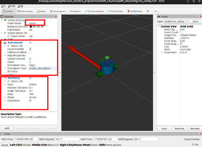
If anything goes right, you should see the Gazebo and Rviz launched. Again, Rviz does not show anything, this time we will choose fixed frame as odom. Add robot model and Odometry. Then save the config file.
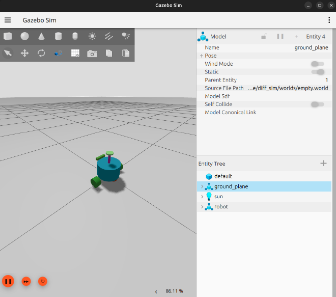
Congratulation! We have succeed launch the differential car in Gazebo and visualize it in Rviz!!!
Control the car#
Section Overview#
In this section, we will control our car and play with it.
Tools#
- VS code
- rqt
Steps#
install the rqt plugin#
To better control the car, install all rqt plugin :
sudo apt install ros-jazzy-rqt-*
launch the simulation and rqt.
control the car using topic#
The diff car was controlled by the plugin we added in the .sdf file. The plugin received a cmd_vel signal translated by bridge. To control the car in gazebo, we need to send cmd_vel signal.
In rqt, choose Plugins -> Topics -> Message Publisher, then choose /cmd_vel as topic, the rqt will automatically select the type:
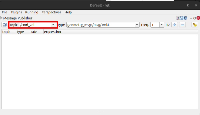
Click the “+” to add a topic, set linear -> x as 0.5, and check the /cmd_vel topic. rqt will publish the topics to control the car. Check the car in Gazebo and Rviz, they should moving. Then change the value of angular -> z as 0.3, the car should turning.
Uncheck the /cmd_vel topic, to stop publish the topic, the car still moving, That’s because the car will follow the last command to move.
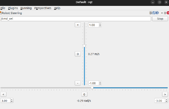
control the car using robot steering#
Choose Plugin -> Robot Tools -> robot steering. You will see the robot control panel. Change some value and see how car react to it.
control the car using game pad#
We could also use game pad to control the robot, connect the game pad, then run:
ros2 launch teleop_twist_joy teleop-launch.py joy_config:=xbox
detailed config and usage can be found on official homepage.
visualize the camera image#
Remember that when modeling the robot, we add depth camera, lidar and imu sensor. We will visualize it now.
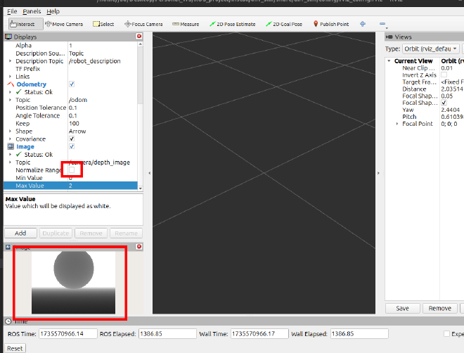
In Rviz, Click Add -> by topic then choose image under depth_image
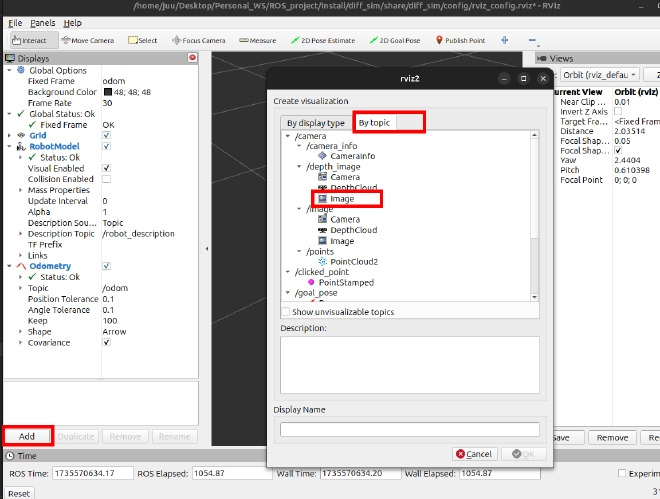
You will see a image window and image topic add to Rviz, but the image seems does not show correctly. Expand Image topic then uncheck Normalize Range, the image will be come normal.
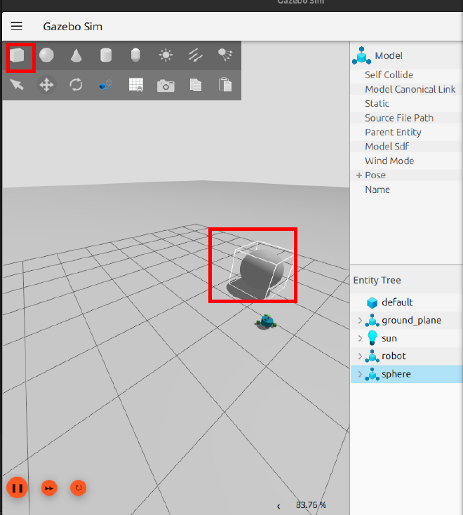
Add some geometry in Gazebo, in front of the car camera, you will see the depth image in Rviz.
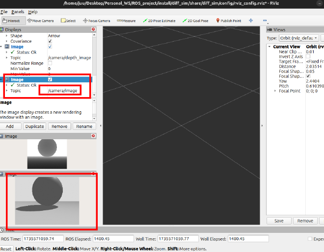
You could also add a normal image in Rviz
visualize depth camera scan point#
Depth camera also has point cloud data. Click Add -> by topic -> PointCloud2
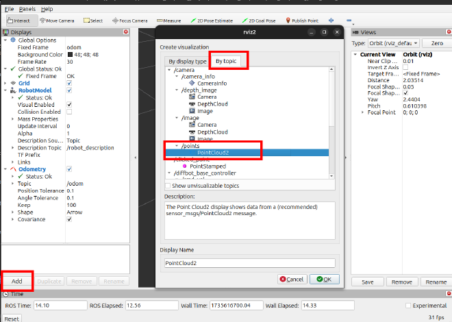
You will get:
visualize lidar scan#
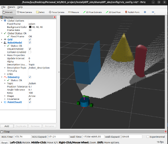
Add more geometry around the car in Gazebo, the click three dots at up right. search Visualize lidar.
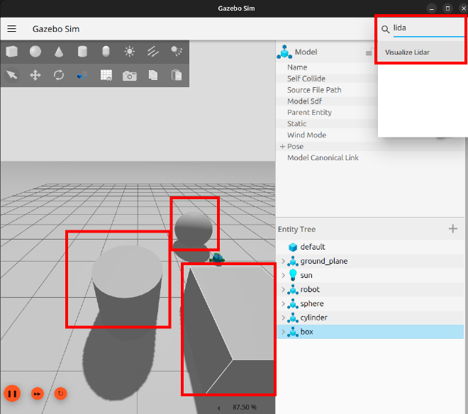
Refresh the topic then the lidar ray will show in Gazebo.
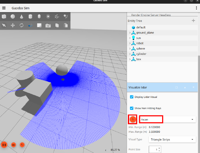
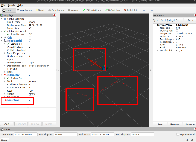
You could also see the lidar date in Rviz, after you add the LaserScan topic.
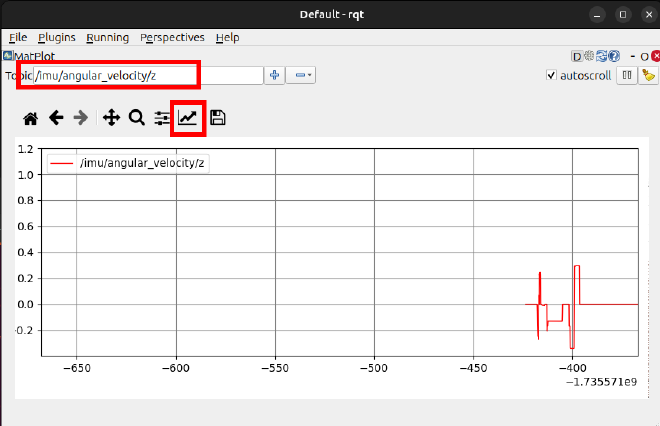
visualize imu sensor signal#
We could also plot the imu signal in rqt. Choose Plugins -> Visualization -> Plot. Then set the topic to be /imu/angular_velocity/z and set proper x range. Then change the car direction, you will see the velocity of z changed.